
Problem
One of our latest jobs was to perform boundary tests of movement sensors. We have measured battery lifespan depending on the type of the movement and data transmission speed.
In simple words: We checked how long will the battery last if we use the device intensively.
The point was: how do we repeat the very same movement for hours, or, possibly, even days. That is when the idea of using a programmable robotic arm came to our minds. As we don’t have one, we decided to build one.
Concept
As a base for the project, we are using an Arduino – a well-known “microcomputer”. It does very well in this kind of projects.
We divided our tutorial into three parts:
- Prototype
- Arm
- Controller
To create an arm, we have used a 3D model found on Thingiverse, which we next printed on the Ender 3 3D printer. The prototype is used to move the arm. The controller was designed from scratch by ourselves and then 3D printed.
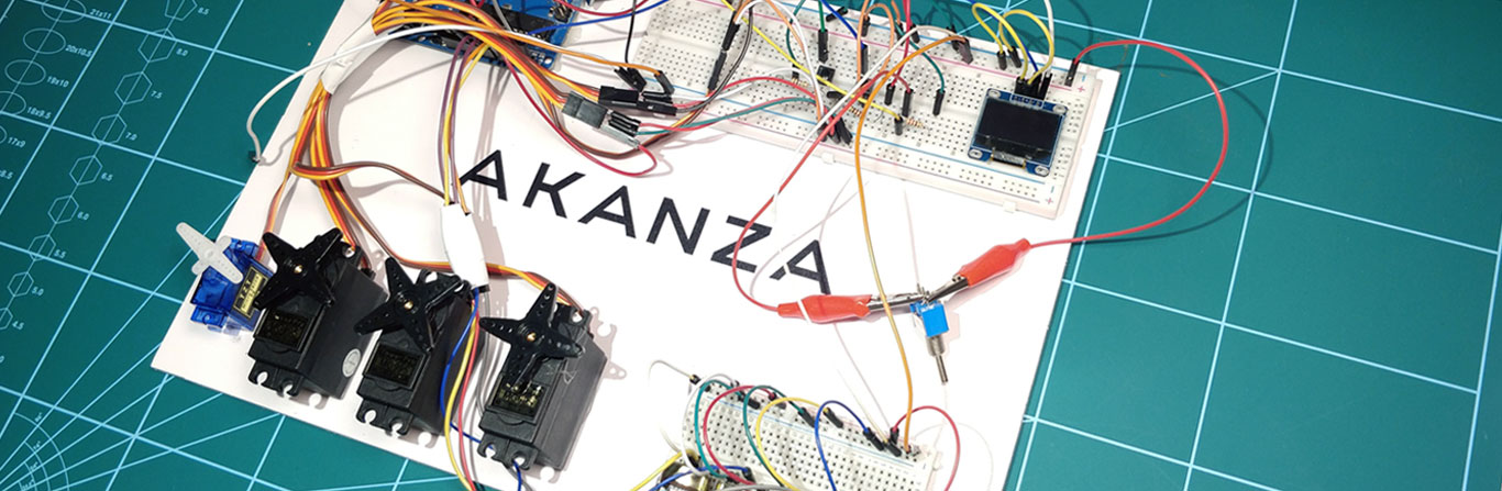
Let’s build a prototype!
In this part of the course, we focus on electronics. Creating a prototype will most likely save us a lot of time later.
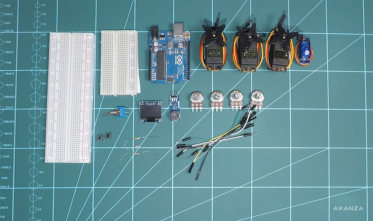
What do we need?
- 2 x Breadboard
- 1 x Arduino UNO
- 3 x Servo motor M955
- 1 x Servo motor SG90
- 4 x Potentiometer B10K
- 1 x Buzzer module (optional)
- 1 x OLED Display 128X64
- 1 x Lever switch
- 2 x Microswitch
- 3 x Resistor 1k
- Cables
A buzzer is optional – we’ll use it to make sure the button was pressed.
Diagram
The undermentioned diagram shows how to connect all of the electronics used to control the arm.
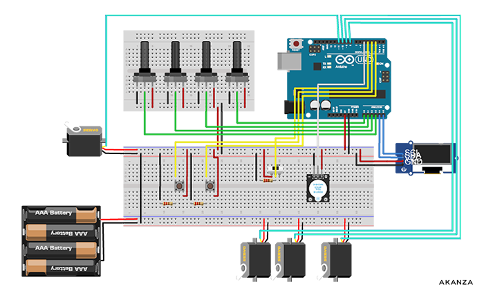
You can download the diagram in high resolution HERE.
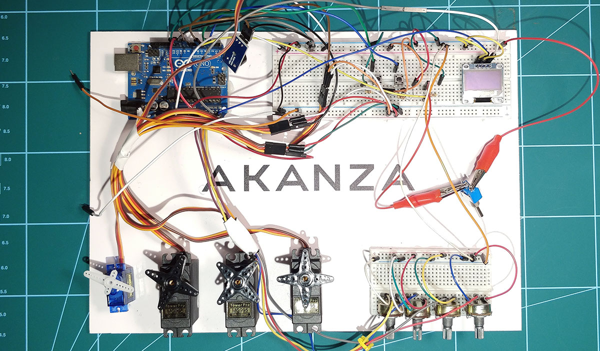
Connecting everything up
Connect every unit from the diagram with Arduino UNO using pins on the breadboard.
- Potentiometers: A0 – A3
- Servo motor M955: D8 – D10
- Servo motor SG90: D11
- Buzzer module: D5
- OLED Display: SDA – A4, SCL – A5
- Button 1: D8
- Button 2: D2
- Lever switch: D4
A – analog pin
D – digital pin
Don’t forget about plugging power supply and ground.
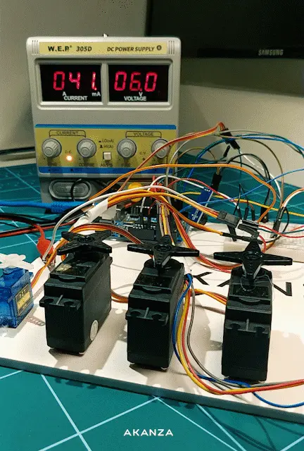
Power supply
We connect Arduino UNO with PSU (or battery) 9V. Potentiometers, OLED Display, buzzer, and buttons will be powered by the Arduino unit using a 5V voltage. We can also power servo motor SG90 by the Arduino as it doesn’t require high voltage.
However, the M955 servo motors require an external power supply. Connecting them to the Arduino may damage our circuit! Servo motor M955 works in limits from 4.7V to 6V. In our prototype, we used a laboratory power supply, but you can use other power sources like batteries or PSU.
The voltage must be within the servo motor limits (the higher the voltage, the faster the servo motor works).
Coding!
How to bring our circuit to life? Of course, we have to program it. We’re going to use Arduino IDE. It’s dedicated to programming microcontrollers such as Arduino, ESP32, etc.
We download the Arduino IDE from HERE. Installation is pretty straightforward.
How do we write a code understandable for our Arduino unit? The C language comes in handy. You’ll find all the code needed to check if the circuit works fine below.
Let’s get to work!
We start our program by including libraries:
#include <Servo.h>
#include <OLED_I2C.h>- Servo.h – servo motors support. It’s one of the standard Arduino libraries – you don’t have to install it.
- OLED_I2C.h – it supports our OLED display. You can download it HERE.
We initialize the display and font size:
OLED  myOLED(SDA, SCL);
extern uint8_t SmallFont[];
Then declare pins, we have connected our devices to:
const int buzzer_pin = 5; // buzzer

const int button_1 = 2; // button 1
const int button_2 = 3; // button 2
const int button_3 = 4; // lever switch

const int joy1 = 0; // potentiometer 1
const int joy2 = 1; // potentiometer 2
const int joy3 = 2; // potentiometer 3
const int joy4 = 3; // potentiometer 4

const int servo_pin_1 = 8; // Servo 1 M955
const int servo_pin_2 = 9; // Servo 2 M955
const int servo_pin_3 = 10; // Servo 3 M955
const int servo_pin_4 = 11; // Servo 4 SG90
We declare variables to store positions of servo motors. We added “old_” variables so we can access the last position of servomotors.
unsigned int servoVal1;
unsigned int servoVal2;
unsigned int servoVal3;
unsigned int servoVal4;

unsigned int old_servoVal1;
unsigned int old_servoVal2;
unsigned int old_servoVal3;
unsigned int old_servoVal4;

Servo servo1; // initialize servo 1
Servo servo2; // initialize servo 2
Servo servo3; // initialize servo 3
Servo servo4; // initialize servo 4
All variables are declared. Now it’s time to declare the start of the program. We use the function “setup” to do this. Every piece of code we write now should be placed inside this function.
void setup()
{
	// instructions
}
We declare which pins are INPUT and OUTPUT pins. In our case, we take input from buttons and the switch. We send data to the buzzer, so it’s an output pin.
pinMode(button_1, INPUT);
pinMode(button_2, INPUT);
pinMode(button_3, INPUT);
pinMode(buzzer_pin, OUTPUT);
Now we assign pins to our servo motors:
servo1.attach(servo_pin_1);
servo2.attach(servo_pin_2);
servo3.attach(servo_pin_3);
servo4.attach(servo_pin_4);
We suggest that you choose the speed (baud) of the serial port we use to communicate with our board. It’s a useful solution in case we have to debug our code.
Serial.begin(9600);The example of testing potentiometers:
Serial.println("Analog 1: " + String(analogRead(joy1)) + " / Analog 2: " + String(analogRead(joy2)) + " / Analog 3: " + String(analogRead(joy3)) + " / Analog 4: " + String(analogRead(joy4)));
We receive the current position of potentiometers and assign them to variables:
servoVal1 = analogRead(joy1);
servoVal2 = analogRead(joy2);
servoVal3 = analogRead(joy3);
servoVal4 = analogRead(joy4);
Then we initialize OLED display:
if (!myOLED.begin(SSD1306_128X32))
while (1); // RAM overload protection

myOLED.setFont(SmallFont); // set font size
myOLED.clrScr(); // clear screen
We show current potentiometers values on the screen:
myOLED.print("A: " + String(servoVal1), LEFT, 1);
myOLED.print("B: " + String(servoVal2), LEFT, 9);
myOLED.print("C: " + String(servoVal3), LEFT, 17);
myOLED.print("D: " + String(servoVal4), LEFT, 25);
myOLED.update();
Explanatory notes:
- Function String() transform value to the text which can be understood by the display
- LEFT – it’s a position of the text on the screen
- 1, 9, 17, 25 – the number of the row/line we display the text from
Controlling the buzzer:
void buzzer(String type) {
	digitalWrite(buzzer_pin, HIGH);
	int delay_buzzer = 10;
	if (type == "long") {
		delay_buzzer = 100;
	}
	digitalWrite(buzzer_pin, LOW);
	delay(delay_buzzer);
	digitalWrite(buzzer_pin, HIGH);
}
It’s an uncomplicated function which, depending on the parameter “type”, activates and deactivates the buzzer for the given amount of time (10ms or 100ms).
What next?
We declared the start of the program. Now it’s time for our circuit to start doing things! We will use a function called “loop()”, where we will write the next part of our code.
void loop()
{
	// instructions
}
Controlling potentiometers and servomotors
- We receive value from potentiometer 1.
- Using function map() we change its value for it to fit between 0 and 180 (tolerance of servo motor).
- We check if the current value of the potentiometer is different than the previous one.
- If so, we change the position of the servo motor
// SERVO 1
servoVal1 = analogRead(joy1);
servoVal1 = map(servoVal1, 0, 1023, 0, 180);
if (servoVal1 != old_servoVal1) {
	old_servoVal1 = servoVal1;
	servo1.write(servoVal1);
}
We do the same with the remaining ones.
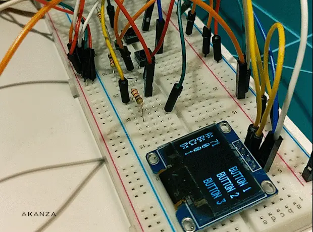
Reading buttons
If one of the buttons is pressed, we show appropriate text on the display and activate the buzzer.
if (digitalRead(button_1) == HIGH) {
	myOLED.print("ON", RIGHT, 1);
	buzzer("short");
} else {
	myOLED.print("BUTTON 1", RIGHT, 1);
}
Showing the values of the potentiometers on the screen:
myOLED.print("A: " + String(servoVal1), LEFT, 1);
myOLED.print("B: " + String(servoVal2), LEFT, 9);
myOLED.print("C: " + String(servoVal3), LEFT, 17);
myOLED.print("D: " + String(servoVal4), LEFT, 25);
myOLED.update();

delay(50); // delay every iteration of a loop
This is it. You can download the whole code here: https://gitlab.akanza.pl/mgolan/akanzaarm
See the video of how did we build the prototype and how does it work.
Stay tuned for next parts of our tutorial on “How to build a robotic arm?“.


